


Contact Us
Tel: 0086 755 23248547
Fax: 0086 755 23248547
Skype:simon9969@hotmail.com
Linkman:Simon Gao
Postcode:518106
Web: www. injection-flow.com
E-mail:simon@mpa-tooling.com
Address: Building Yonghui, No. 202, Changchun north Road, Guangming new district, Shenzhen city, China
Cad to Mold flow
Interfacing CAD to Mold flow
MPA and partner companies have a wide CAD interfacing capability and are able to communicate via most popular CAD software packages and interface standards.
A Mold flow simulation is generally based on a triangular finite element mesh. The mesh is created over a CAD representation of the product and forms a geometric mathematical description of the part. A wide range of CAD interfaces enable MPA to import a CAD solid model and create a uniform FEA mesh over the entire surface of the product.
MPA are able to supply other Mold flow users with a high quality accurate mesh ready to run, and usually in a matter of day's. Contact us for more information on outsourcing your meshing requirements.
MPA have extensive experience with all Mold flow mesh types including:
Fusion Mesh
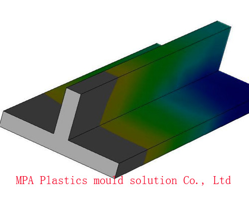 Fusion- Dual Domain - Ideal for basic filling analysis.
 Initial results delivered very quickly. Works well on parts with uniform wall thickness.
Mid-Plane Mesh
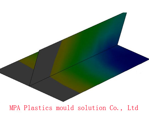 Midplane- More complex model conversion from CAD than either 3D or Fusion mesh,
but very detailed results and extensive capability. Our favorite for complex filling cooling
& warpage analysis jobs including fiber orientation.
Midplane- More complex model conversion from CAD than either 3D or Fusion mesh,
but very detailed results and extensive capability. Our favorite for complex filling cooling
& warpage analysis jobs including fiber orientation.
3D Tetrahedral Mesh
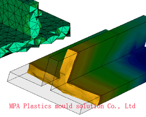 3D Mesh- Based on a Tetrahedral mesh for true 3D simulation through the part thickness. Ideal for analysing parts
with a wide variation in thickness. The simulation shows results through the entire part thickness,
predicts jetting and is excellent for Gas Injection simulation.
3D Mesh- Based on a Tetrahedral mesh for true 3D simulation through the part thickness. Ideal for analysing parts
with a wide variation in thickness. The simulation shows results through the entire part thickness,
predicts jetting and is excellent for Gas Injection simulation.
CAD Interface Capability:
MPA employ Mold flow Design Link ( MDL ) for direct interface from CAD formats including: STEP, IGES, STL and PARASOLIDS. Other programs such as Altair Hypermesh expand our capability for producing complex mesh geometries from almost any CAD format.
Pro/Engineer V18 V19 V.20 2000i ......2000i2, 2001, WF1,WF2(.prt)
Unigraphics V14/V15/V16 File V17/V18/V19/NX1/NX2/ NX3(.prt)
STEP AP203/204 File (.stp)
Parasolid File V10/V9.1 V11\12\13\14\15 (.x_b) (.x_t) Cadkey (.prt, .cdk) Solid edge (.par) Inventor (.ipt)
SolidWorks 98/98/99/2000/1/2/3/4/5/6 File (.prt).
ACIS File (.sat)
SDRC Ideas V6 and V7/8/9/NX10
Catia file V4, V5, V5R16 (*.CATPart, *.model, *.asm, *.CATProduct)
FEA Interface Capability:
Patran, *.pat
Nastran, *.nas and *.bdf
Ansys Prep 7, *.ans
Ideas Univeral File *.unv
C-Mold *.CMF files
2005-2015 © Copyright MPA Mold flow analysis Tel:0086 755 23248547 Fax:0086 755 23248547
Sales Representative:simon@mpa-tooling.com