


Contact Us
Tel: 0086 755 23248547
Fax: 0086 755 23248547
Skype:simon9969@hotmail.com
Linkman:Simon Gao
Postcode:518106
Web: www. injection-flow.com
E-mail:simon@mpa-tooling.com
Address: Building Yonghui, No. 202, Changchun north Road, Guangming new district, Shenzhen city, China
Mold flow Options
Mold flow Analysis Options
Fiber Orientation, Gas injection, Over molding, Metal Inserts, In Mold Decoration and Core Shift.
MPA have continually updated and expanded their plastics simulation tools and have a wide capability in the field of plastics injection moulding simulation:
Most options are available with basic FEA model types including, 3D tetrahedral, Mid-plane and Fusion / Dual Domain mesh formats.
Fiber Orientation
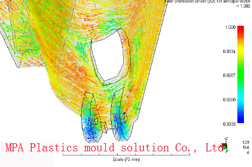 The Fiber-orientation flow analysis is used to predict the behavior of composite materials. While injection-molded fiber-reinforced
thermoplastics constitute a major commercial application of short-fiber composite (a filler within a polymer matrix) materials,
the modeling of the process is more complex than in other flow applications.
The Fiber-orientation flow analysis is used to predict the behavior of composite materials. While injection-molded fiber-reinforced
thermoplastics constitute a major commercial application of short-fiber composite (a filler within a polymer matrix) materials,
the modeling of the process is more complex than in other flow applications. In injection-molded composites, the fiber alignment (or orientation) distributions show a layered nature, and are affected by the filling speed, the processing conditions and material behavior, plus the fiber aspect ratio and concentration. Without proper consideration of the fiber behavior, there is a tendency to significantly overestimate the orientation levels. The Mold flow fiber orientation model allows significantly improved orientation prediction accuracy over a range of materials and fiber contents.
Fiber / Polymer composite materials simulation:
Predict fiber orientation and thermo-mechanical property distributions in the molded part
Predict elastic modulus and average modulus in the flow and transverse-flow directions
Predict linear thermal expansion coefficient (LTEC) and average LTEC
Calculate Poisson's Ratio, a measure of the transverse contraction of a part compared to its length when exposed to tensile stress
Optimize filling pattern and fiber orientation to reduce shrinkage variations and part warpage
Gas Injection
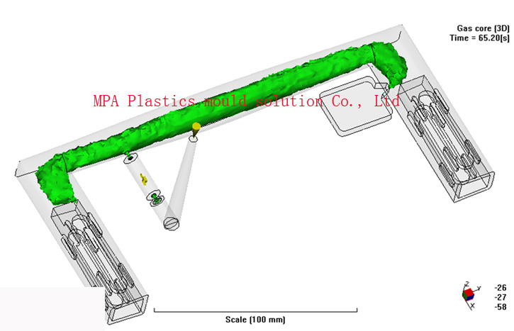 Gas-Assisted Injection Molding is a process where an inert gas is introduced at pressure, into the polymer melt stream at the end of the polymer injection phase. The gas injection displaces the molten polymer core ahead of the gas, into the as yet unfilled sections of the mold, and compensates for the effects of volumetric shrinkage, thus completing the filling and packing phases of the cycle and producing a hollow part.
Traditionally, injection molded components have been designed with a relatively constant wall thickness throughout the component. This design guideline helps to avoid major flaws or defects such as sink marks and warpage. However, apart from the simplest of parts, it is impossible to design a component where all sections are of identical thickness. These variations in wall thickness result in different sections of the part packing differently, which in turn means that there will be differentials in shrinkage throughout the molding and that subsequently distortion and sinkage can often occur in these situations.
Gas Injection Capability:
Gas injection allows cost effective production of components with:
Thick section geometry.
No sink marks.
Minimal internal stresses.
Reduced warpage.
Low clamp pressures.
Evaluate the filling pattern with the influence of gas injection to aid in part design, gate placement, and process setup
Properly size gas channels for optimal filling and gas penetration
Determine the best gas channel layout to control gas penetration
Inject gas at any location or in multiple locations within the part or runner system
Inject gas through multiple gas pins simultaNeo™usly or at different times during the process
Detect areas of poor gas penetration or other problems
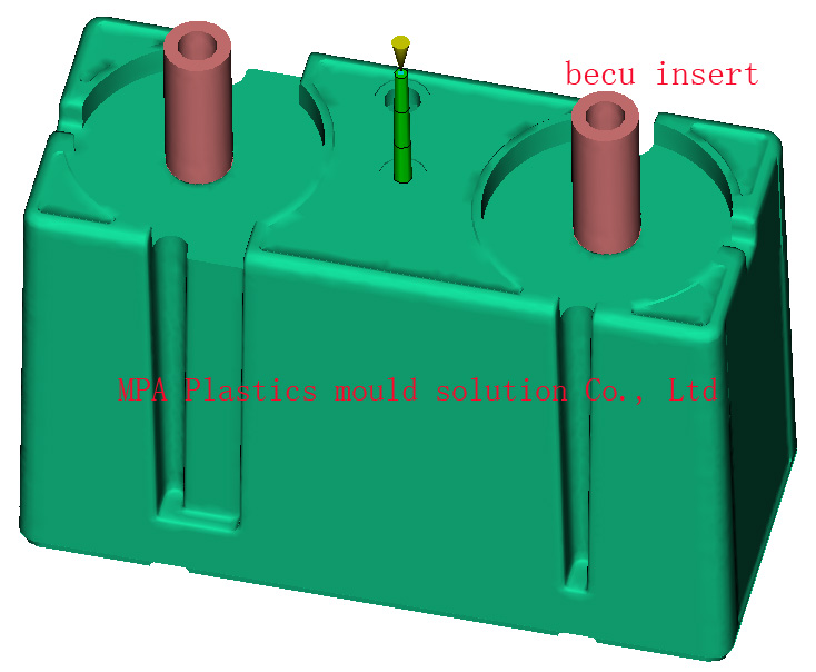
Over molding, Metal Inserts
In-mold labels are very thin inserts usually less than 1mm thick. Labels are applied to the mold before each injection cycle. The labels normally have different material properties can affect the flow and cooling behavior. An insert is a component that is placed into the mold before the injection phase and is anchored into the plastic part by being partially or wholly surrounded by the injected plastic. Typical inserts may have threads, may be electrically conductive, or may be a different plastic material.
 |
 |
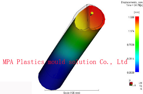
Core Shift
Core Shift Analysis – Mold flow provides a unique multi-physics solution to simulate injection mold core shift, which is defined as the movement of a core caused by non-uniform pressure distribution during the filling and packing stages of the injection molding process. Core shift typically causes molded part wall thickness variation which can result in both structural and cosmetic defects
Core shift can result in undesirable variations in wall thickness which will affect the final shape and mechanical performance of the part. The core shift simulation provides detailed information about the movement of the mold core and its interaction with the polymer flow process as the plastic is being injected. Designers can use this information to correct for the core shift phenomenon, for example, by modifying the design of the part, or adjusting process conditions such as the gate location or core/mold temperatures.
2005-2015 © Copyright MPA Mold flow analysis Tel:0086 755 23248547 Fax:0086 755 23248547
Sales Representative:simon@mpa-tooling.com